Over the past 40 years, Sigma Tek has custom designed and manufactured reliable,
proven instruments for virtually every type of aircraft that flies. This includes precision modular
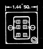
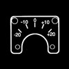
instrumentation configured to customer's exact specifications. Cluster modules measure 1.44" square, and
can be arranged in almost any combination for optimum panel utilization. Individual modules are easily
removed for calibration and service.
Customization of display graphics, scale ranges, range marks, colors, and internal lighting,
all ensure performance and appearance compatibility with individual aircraft systems
and instrument panels.
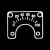
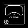
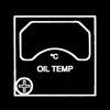
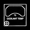
- Oil
Temp
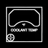
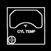
- Cyl
Temp
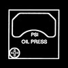
- Oil
Press
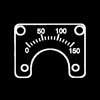
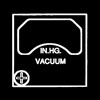
- Vac
Air
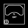
- Air
Temp
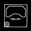
- Fuel
Qty
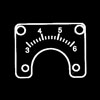
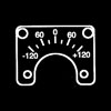
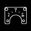
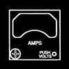
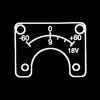
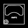
- Amps
- Volt
Amp
- Volts
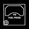
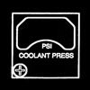
- Fuel
Press
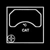
- Carb
Temp
- Case
Assemblies
- Customer
Specs
|
|
|
|
|
|
- Dial & Bezel Graphics: Letters, numerals & grads to be white on black background.
- Lighting: Blue-White color
- Range marks:
Colors:
- Green per 8A070-001
- Yellow per 8A059-009
- Blue per 8A059-014
- Red per 8A060-006
Size:
- Arcs (0.06 wide)
- Lines (0.03 x 0.12)
- This unit is approved per FAA TSO-C43, Type I
- This unit is calibrated to operate with Sigma-Tek probe part number: S21023-001.
|
| Sigma-Tek P/N S24003-004P |
| Sigma-Tek P/N S24003-004S |
| |
| Pin 1: |
+14 or 28 VDC |
| Pin 2: |
Ground (indicator) |
| Pin 3: |
Transmitter Signal |
| Pin 4: |
+14 or 28 VDC Lights |
| Pin 5: |
Open |
| Pin 6: |
Open |
| Pin 7: |
Ground (lighting) |
|
|
| Bezel 1 |
Bezel 2 |
Bezel 3 |
Bezel 4 |
 |
 |
 |
 |
| A/W 5B845-001 |
A/W 5B845-002 |
A/W 5B845-022 |
A/W 5B845-023 |
|
| |
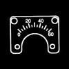
| Reading (°F) |
Test (ohms) |
Tolerance (± °F) |
| 0 |
84.50 |
5 |
| 50 |
93.50 |
5 |
| 100 |
103.78 |
5 |
| 150 |
114.50 |
5 |
| 200 |
125.98 |
5 |
| 250 |
138.30 |
5 |
Friction Error (±5 °F) |
Position Error (±5 °F) |
|
|
|
|
| Reading (°F) |
Test (ohms) |
Tolerance (± °F) |
| 50 |
93.50 |
5 |
| 100 |
103.78 |
5 |
| 150 |
114.50 |
5 |
| 200 |
125.98 |
5 |
| 250 |
138.30 |
5 |
| 300 |
151.33 |
5 |
Friction Error (±5 °F) |
Position Error (±5 °F) |
|
|
|
|
| Reading (°C) |
Test (ohms) |
Tolerance (± °C) |
| 0 |
90.38 |
3 |
| 50 |
108.39 |
3 |
| 100 |
128.85 |
3 |
| 150 |
151.91 |
3 |
Friction Error (±3 °C) |
Position Error (±3 °C) |
|
| |
|
|
|
|
|
|
|
- Dial & Bezel Graphics: Letters, numerals & grads to be white on black background.
- Lighting: Blue-White color
- Range marks:
Colors:
- Green per 8A070-001
- Yellow per 8A059-009
- Blue per 8A059-014
- Red per 8A060-006
Size:
- Arcs (0.06 wide)
- Lines (0.03 x 0.12)
- This unit is approved per FAA TSO-C43, Type I
- This unit is calibrated to operate with Sigma-Tek probe part number: S21024-001.
|
| Sigma-Tek P/N S24003-004P |
| Sigma-Tek P/N S24003-004S |
| Pin 1: |
+14 or 28 VDC |
| Pin 2: |
Ground (indicator) |
| Pin 3: |
Transmitter Signal |
| Pin 4: |
+14 or 28 VDC Lights |
| Pin 5: |
Open |
| Pin 6: |
Open |
| Pin 7: |
Ground (lighting) |
|
|
| Bezel 1 |
Bezel 2 |
|
|
 |
 |
 |
|
| A/W 5B845-003 |
A/W 5B845-004 |
|
|
|
|
|
| Reading (°F) |
Test (ohms) |
Tolerance (± °F) |
| 0 |
45.20 |
12 |
| 200 |
76.80 |
12 |
| 400 |
118.20 |
12 |
| 600 |
173.80 |
12 |
Friction Error (±12 °F) |
Position Error (±12 °F) |
|
|
|
|
| Reading (°F) |
Test (ohms) |
Tolerance (± °F) |
| 200 |
76.80 |
12 |
| 300 |
96.00 |
12 |
| 400 |
118.20 |
12 |
| 500 |
143.80 |
12 |
| 600 |
173.80 |
12 |
Friction Error (±12 °F) |
Position Error (±12 °F) |
|
|
|
|
| Reading (°C) |
Test (ohms) |
Tolerance (± °C) |
| 0 |
50.00 |
6 |
| 100 |
79.00 |
6 |
| 200 |
116.50 |
6 |
| 300 |
164.50 |
6 |
Friction Error (±6 °C) |
Position Error (±6 °C) |
|
| |
|
|
|
|
|
|
|
- Dial & Bezel Graphics: Letters, numerals & grads to be white on black background.
- Lighting: Blue-White color
- Range marks:
Colors:
- Green per 8A070-001
- Yellow per 8A059-009
- Blue per 8A059-014
- Red per 8A060-006
Size:
- Arcs (0.06 wide)
- Lines (0.03 x 0.12)
- This unit is approved per FAA TSO-C47, Type II
- This unit is calibrated to operate with Sigma-Tek 100 or 150 PSI pressure transducer Sigma-Tek part number: S18015-006 or S18015-008.
|
| Sigma-Tek P/N S24003-004P |
| Sigma-Tek P/N S24003-004S |
| Pin 1: |
+14 or 28 VDC |
| Pin 2: |
Ground (indicator) |
| Pin 3: |
+8 V to Transmitter (14 VDC)
+10 V to Transmitter (28 VDC) |
| Pin 4: |
Signal from Transmitter |
| Pin 5: |
+14 or +28 VDC Lights |
| Pin 6: |
Open |
| Pin 7: |
Ground (lighting) |
|
|
| Bezel 1 |
Bezel 2 |
|
|
 |
 |
|
|
| A/W 5B845-005 |
A/W 5B845-021 |
|
|
|
| |
| Reading (psi) |
14V Unit |
28V Unit |
Tolerance (±psi) |
| 0 |
1.00 |
1.25 |
3 |
| 20 |
2.00 |
2.50 |
3 |
| 40 |
3.00 |
3.75 |
3 |
| 60 |
4.00 |
5.00 |
3 |
| 80 |
5.00 |
6.25 |
3 |
| 100 |
6.00 |
7.50 |
3 |
Friction Error (±3 psi) |
Position Error (±3 psi) |
|
|
|
|
| Reading (psi) |
14V Unit |
28V Unit |
Tolerance (±psi) |
| 0 |
1.00 |
1.25 |
4.5 |
| 50 |
2.67 |
3.33 |
4.5 |
| 100 |
4.33 |
5.42 |
4.5 |
| 150 |
6.00 |
7.50 |
4.5 |
Friction Error (±4.5 psi) |
Position Error (±4.5 psi) |
|
|
|
|
|
|
|
|
- Dial & Bezel Graphics: Letters, numerals & grads to be white on black background.
- Lighting: Blue-White color
- Range marks:
Colors:
- Green per 8A070-001
- Yellow per 8A059-009
- Blue per 8A059-014
- Red per 8A060-006
Size:
- Arcs (0.06 wide)
- Lines (0.03 x 0.12)
- This unit is approved per FAA TSO-C47, Type II
- This unit is calibrated to operate with Micro Switch® 5 PSI pressure transducer 142PC05D for P.C. board mounting.
|
| Sigma-Tek P/N S24003-004P |
| Sigma-Tek P/N S24003-004S |
| Pin 1: |
+14 or 28 VDC |
| Pin 2: |
Ground (indicator) |
| Pin 3: |
+8 V to Transmitter (14 VDC)
+10 V to Transmitter (28 VDC) |
| Pin 4: |
Signal from Transmitter |
| Pin 5: |
+14 or +28 VDC Lights |
| Pin 6: |
Open |
| Pin 7: |
Ground (lighting) |
|
|
| Bezel 1 |
Bezel 2 |
|
|
 |
 |
|
|
| A/W 5B845-006 |
A/W 5B845-024 |
|
|
|
|
| Reading (psi) |
14V Unit |
28V Unit |
Tol. (±volts) |
Tol. (±in.hg.) |
| 3 |
2.47 |
3.09 |
0.045 |
0.075 |
| 4 |
2.96 |
3.70 |
0.045 |
0.075 |
| 5 |
3.45 |
4.31 |
0.045 |
0.075 |
| 6 |
3.94 |
4.92 |
0.045 |
0.075 |
Friction Error (±0.075 in.hg.) |
Position Error (±0.075 in.hg.) |
|
| |
|
|
|
|
|
|
- Dial & Bezel Graphics: Letters, numerals & grads to be white on black background.
- Lighting: Blue-White color
- Range marks:
Colors:
- Green per 8A070-001
- Yellow per 8A059-009
- Blue per 8A059-014
- Red per 8A060-006
Size:
- Arcs (0.06 wide)
- Lines (0.03 x 0.12)
- This unit is approved per FAA TSO-C43, Type I
- This unit is calibrated to operate with Sigma-Tek probe part number: S21023-001.
|
| Sigma-Tek P/N S24003-004P |
| Sigma-Tek P/N S24003-004S |
| Pin 1: |
+14 or 28 VDC |
| Pin 2: |
Ground (indicator) |
| Pin 3: |
Transmitter Signal |
| Pin 4: |
+14 or 28 VDC Lights |
| Pin 5: |
Open |
| Pin 6: |
Open |
| Pin 7: |
Ground (lighting) |
|
|
|
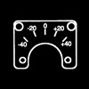
| Reading (°C) |
Test (ohms) |
Tolerance (± °C) |
| -40 |
77.39 |
1.5 |
| -20 |
83.77 |
1.5 |
| 0 |
90.38 |
1.5 |
| +20 |
97.31 |
1.5 |
| +40 |
104.60 |
1.5 |
Friction Error (±1.5 °C) |
Position Error (±1.5 °C) |
|
| |
|
|
|
|
|
|
- Dial & Bezel Graphics: Letters, numerals & grads to be white on black background.
- Lighting: Blue-White color
- Range marks:
Colors:
- Green per 8A070-001
- Yellow per 8A059-009
- Blue per 8A059-014
- Red per 8A060-006
Size:
- Arcs (0.06 wide)
- Lines (0.03 x 0.12)
- This unit is approved per FAA TSO-C55, Type I
- This unit is designed to operate with resistance type transmitter. Resistance data to be supplied by customer.
|
| Sigma-Tek P/N S24003-004P |
| Sigma-Tek P/N S24003-004S |
| Pin 1: |
+14 or 28 VDC |
| Pin 2: |
Ground (indicator) |
| Pin 3: |
Transmitter Signal |
| Pin 4: |
+14 or 28 VDC Lights |
| Pin 5: |
Open |
| Pin 6: |
Open |
| Pin 7: |
Ground (lighting) |
|
|
| Bezel 1: A/W 5B845-008 |
| Dash
No. |
Bezel
No. |
Bezel
Text |
A/W
5B845- |
| -6 |
#1 |
FUEL QTY |
008 |
| -61 |
#2 |
RIGHT FUEL QTY |
009 |
| -62 |
#3 |
LEFT FUEL QTY |
010 |
| -63 |
#4 |
AUX FUEL QTY |
011 |
| -64 |
#5 |
R. AUX FUEL QTY |
012 |
| -65 |
#6 |
L. AUX FUEL QTY |
013 |
| -66 |
#7 |
MAIN FUEL QTY |
017 |
| -67 |
#8 |
TIP FUEL QTY |
018 |
|
 |
|
|
| Reading |
Test (ohms) |
Tolerance (±in.) |
| E |
| |
+0, -1/32 |
| 1/4 |
| |
1/32 |
| 1/2 |
Customer Provided |
1/32 |
| 3/4 |
| |
1/32 |
| F |
| |
+1/32, -0 |
Friction Error (±1/32) |
Position Error (±1/32) |
|
| |
|
|
|
|
|
|
- Dial & Bezel Graphics: Letters, numerals & grads to be white on black background.
- Lighting: Blue-White color
- Range marks:
Colors:
- Green per 8A070-001
- Yellow per 8A059-009
- Blue per 8A059-014
- Red per 8A060-006
Size:
- Arcs (0.06 wide)
- Lines (0.03 x 0.12)
- This unit is calibrated to operate with a 50 mv shunt Sigma-Tek part number 22-370-60 for 60 amps; 22-370-120 for 120 amps; 22-370-20 for 20 amps.
|
| Sigma-Tek P/N S24003-004P |
| Sigma-Tek P/N S24003-004S |
| Pin 1: |
+14 or 28 VDC |
| Pin 2: |
+AMPS |
| Pin 3: |
-AMPS |
| Pin 4: |
+14 or 28 VDC Lights |
| Pin 5: |
Open |
| Pin 6: |
Open |
| Pin 7: |
Ground (lighting) |
|
|
| Bezel 1 |
Bezel 2 |
|
|
 |
 |
|
|
| A/W 5B845-014 |
A/W 5B845-019 |
|
|
|
|
| Reading |
Test (mv) |
Tolerance (±amps) |
| 0 |
0.00 |
3 |
| 20 |
17.60 |
3 |
| 40 |
35.20 |
3 |
| 60 |
50.00 |
3 |
Friction Error (±3 amps) |
Position Error (±3 amps) |
|
|
|
|
| Reading |
Test (mv) |
Tolerance (±in) |
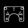
| DIS |
-50 |
0.03 |
| 0 |
0 |
0.03 |
| CHG |
+50 |
0.03 |
Friction Error (±0.03 inches) |
Position Error (±0.03 inches) |
|
|
|
|
| Reading |
Test (mv) |
Tolerance (±amps) |
| -60 |
-50 |
3 |
| -30 |
-25 |
3 |
| 0 |
0 |
3 |
| +30 |
+25 |
3 |
| +60 |
+50 |
3 |
Friction Error (±3 amps) |
Position Error (±3 amps) |
|
| |
|
|
| Reading |
Test (mv) |
Tolerance (±amps) |
| -120 |
-50 |
12 |
| -60 |
-25 |
12 |
| 0 |
0 |
12 |
| +60 |
+25 |
12 |
| +120 |
+50 |
12 |
Friction Error (±12 amps) |
Position Error (±12 amps) |
|
| |
|
|
| Reading |
Test (mv) |
Tolerance (±amps) |
| 0 |
0 |
1 |
| 10 |
25 |
1 |
| 20 |
50 |
1 |
Friction Error (±1 amp) |
Position Error (±1 amp) |
|
| |
|
|
|
|
|
|
- Dial & Bezel Graphics: Letters, numerals & grads to be white on black background.
- Lighting: Blue-White color
- Range marks:
Colors:
- Green per 8A070-001
- Yellow per 8A059-009
- Blue per 8A059-014
- Red per 8A060-006
Size:
- Arcs (0.06 wide)
- Lines (0.03 x 0.12)
- This unit is calibrated to operate with a 50 mv shunt Sigma-Tek part number 22-370-60.
|
| Sigma-Tek P/N S24003-004P |
| Sigma-Tek P/N S24003-004S |
| Pin 1: |
Ground (indicator) |
| Pin 2: |
+SHUNT |
| Pin 3: |
-SHUNT |
| Pin 4: |
+14 or 28 VDC Lights |
| Pin 5: |
Open |
| Pin 6: |
Open |
| Pin 7: |
Ground (lighting) |
|
|
|
| Reading (amps) |
Test (mv) |
Tolerance (±mv) |
| -60 |
-50 |
5 |
| 0 |
0 |
5 |
| +60 |
+50 |
5 |
Friction Error (±5 mv) |
Position Error (±5 mv) |
|
|
| Reading (amps) |
Test (mv) |
Tolerance (±mv) |
| 9 |
9 |
0.5 |
| 18 |
18 |
0.5 |
Friction Error (±0.5 volts) |
Position Error (±0.5 volts) |
|
| |
|
| |
|
|
| Reading (amps) |
Test (mv) |
Tolerance (±mv) |
| -60 |
-50 |
5 |
| 0 |
0 |
5 |
| +60 |
+50 |
5 |
Friction Error (±5 mv) |
Position Error (±5 mv) |
|
| |
| 18 |
18 |
1 |
| 32 |
32 |
1 |
Friction Error (±0.5 volts) |
Position Error (±0.5 volts) |
| |
|
|
|
|
|
|
- Dial & Bezel Graphics: Letters, numerals & grads to be white on black background.
- Lighting: Blue-White color
- Range marks:
Colors:
- Green per 8A070-001
- Yellow per 8A059-009
- Blue per 8A059-014
- Red per 8A060-006
Size:
- Arcs (0.06 wide)
- Lines (0.03 x 0.12)
|
| Sigma-Tek P/N S24003-004P |
| Sigma-Tek P/N S24003-004S |
| Pin 1: |
+VOLTS |
| Pin 2: |
-VOLTS |
| Pin 3: |
Open |
| Pin 4: |
+14 or 28 VDC Lights |
| Pin 5: |
Open |
| Pin 6: |
Open |
| Pin 7: |
Ground (lighting) |
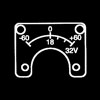
|
|
|
| Reading |
Test (volts) |
Tolerance (±volts) |
| 0 |
0 |
2 |
| 8 |
8 |
2 |
| 16 |
16 |
2 |
| 24 |
24 |
2 |
| 32 |
32 |
2 |
Friction Error (±2 volts) |
Position Error (±2 volts) |
|
|
|
|
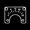
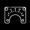
| Reading |
Test (volts) |
Tolerance (±volts) |
| 0 |
0 |
1 |
| 4 |
4 |
1 |
| 8 |
8 |
1 |
| 12 |
12 |
1 |
| 16 |
16 |
1 |
Friction Error (±1 volt) |
Position Error (±1 volt) |
|
| |
|
|
|
|
|
|
- Dial & Bezel Graphics: Letters, numerals & grads to be white on black background.
- Lighting: Blue-White color
- Range marks:
Colors:
- Green per 8A070-001
- Yellow per 8A059-009
- Blue per 8A059-014
- Red per 8A060-006
Size:
- Arcs (0.06 wide)
- Lines (0.03 x 0.12)
- This unit is approved per FAA TSO-C47, Type II
- This unit is calibrated to operate with Sigma-Tek pressure transducer Sigma-Tek part number: S18014-001 (for Dial 1) or S18015-006 (for Dial 2).
|
| Sigma-Tek P/N S24003-004P |
| Sigma-Tek P/N S24003-004S |
| Pin 1: |
+14 or 28 VDC |
| Pin 2: |
Ground (indicator) |
| Pin 3: |
+8 V to transmitter (14 VDC)
-> (S18015-006)
+14 V to transmitter (14 VDC)
-> (S18014-001)
+10 V to transmitter (28 VDC)
-> (S18015-006)
+10 V to transmitter (28 VDC)
-> (S18014-001) |
| Pin 4: |
Signal from Transmitter |
| Pin 5: |
+14 or +28 VDC Lights |
| Pin 6: |
Open |
| Pin 7: |
Ground (lighting) |
|
|
|
| Reading (psi) |
Test (volts) |
Tolerance (±psi) |
| 0 |
1.00 |
0.3 |
| 5 |
2.66 |
0.3 |
| 10 |
4.33 |
0.3 |
| 15 |
6.00 |
0.3 |
Friction Error (±0.3 psi) |
Position Error (±0.3 psi) |
|
|
|
|
| Reading (psi) |
14V Unit (v) |
28V Unit (v) |
Tolerance (±psi) |
| 0 |
1.00 |
1.25 |
1.25 |
| 10 |
1.50 |
1.88 |
1.25 |
| 20 |
2.00 |
2.50 |
1.25 |
| 30 |
2.50 |
3.12 |
1.25 |
| 40 |
3.00 |
3.75 |
1.25 |
| 50 |
3.50 |
4.38 |
1.25 |
Friction Error (±1.25 psi) |
Position Error (±1.25 psi) |
|
| |
|
|
|
|
|
|
- Dial & Bezel Graphics: Letters, numerals & grads to be white on black background.
- Lighting: Blue-White color
- Range marks:
Colors:
- Green per 8A070-001
- Yellow per 8A059-009
- Blue per 8A059-014
- Red per 8A060-006
Size:
- Arcs (0.06 wide)
- Lines (0.03 x 0.12)
- This unit is approved per FAA TSO-C43, Type I
- This unit is calibrated to operate with B-5 probe.
|
| Sigma-Tek P/N S24003-004P |
| Sigma-Tek P/N S24003-004S |
| Pin 1: |
+14 or 28 VDC |
| Pin 2: |
Ground (indicator) |
| Pin 3: |
Transmitter Signal |
| Pin 4: |
+14 or 28 VDC Lights |
| Pin 5: |
Open |
| Pin 6: |
Open |
| Pin 7: |
Ground (lighting) |
|
|
|
| Reading (°C) |
Test (ohms) |
Tolerance (± °C) |
| -20 |
83.77 |
1.0 |
| -10 |
87.04 |
1.0 |
| 0 |
90.38 |
1.0 |
| +10 |
93.80 |
1.0 |
| +20 |
97.31 |
1.0 |
Friction Error (±1.0 °C) |
Position Error (±1.0 °C) |
|
| |
|
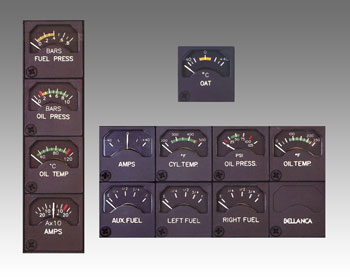 |
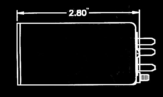
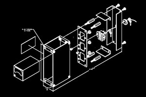
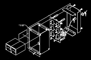
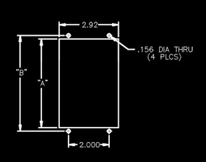
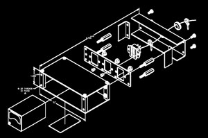
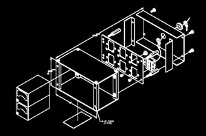
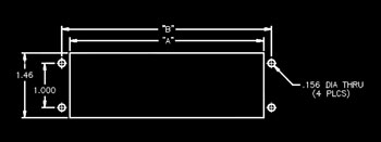
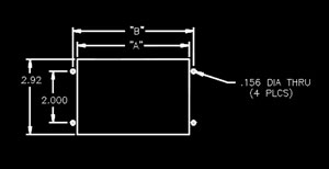
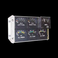
The 169CL-series of cluster modules is highly customizable. Many configurations are available to mount modules in many different positions, in vertical or horizontal layouts. All modules in the series share a common rear connector, allowing flexibility in their positioning within a case assembly. The connector mounting plate, into which the individual modules connect, is wired to the rear avionics connector by the customer according to his specific requirements. This makes it possible to match connector pin outs in existing aircraft wiring harnesses. Optionally, case assemblies can be pre-wired at our factory per customer specifications. Call us with your requirements. |
|
|
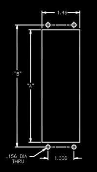
Module
Count |
Width
'A' |
Height
'B' |
Depth
'C' |
Case
Weight |
Weight
(w/ modules) |
| 1 |
1.46 |
1.816 |
2.19 |
0.28 lb |
0.50 lb |
| 2 |
2.90 |
3.256 |
3.63 |
TBD |
TBD |
| 3 |
4.34 |
4.696 |
5.07 |
TBD |
TBD |
| 4 |
5.78 |
6.136 |
6.51 |
TBD |
TBD |
| 5 |
7.22 |
7.576 |
7.95 |
TBD |
TBD |
| 6 |
8.66 |
9.016 |
9.39 |
TBD |
TBD |
| 7 |
10.10 |
10.456 |
10.83 |
TBD |
TBD |
| 8 |
11.54 |
11.896 |
12.27 |
TBD |
TBD |
|
Module
Count |
Width
'A' |
Height
'B' |
Depth
'C' |
Case
Weight |
Weight
(w/ modules) |
| 2 |
1.46 |
1.816 |
2.19 |
TBD |
TBD |
| 4 |
2.90 |
3.256 |
3.63 |
TBD |
TBD |
| 6 |
4.34 |
4.696 |
5.07 |
0.69 lb |
2.00 lb |
| 8 |
5.78 |
6.136 |
6.51 |
.083 lb |
2.60 lb |
| 10 |
7.22 |
7.576 |
7.95 |
0.93 lb |
3.07 lb |
|
|
|
Module
Count |
Width
'A' |
Height
'B' |
Depth
'C' |
Case
Weight |
Weight
(w/ modules) |
| 1 |
1.46 |
1.816 |
2.19 |
0.28 lb |
0.50 lb |
| 2 |
2.90 |
3.256 |
3.63 |
TBD |
TBD |
| 3 |
4.34 |
4.696 |
5.07 |
TBD |
TBD |
| 4 |
5.78 |
6.136 |
6.51 |
TBD |
TBD |
| 5 |
7.22 |
7.576 |
7.95 |
TBD |
TBD |
| 6 |
8.66 |
9.016 |
9.39 |
TBD |
TBD |
| 7 |
10.10 |
10.456 |
10.83 |
TBD |
TBD |
| 8 |
11.54 |
11.896 |
12.27 |
TBD |
TBD |
|
Module
Count |
Width
'A' |
Height
'B' |
Depth
'C' |
Case
Weight |
Weight
(w/ modules) |
| 2 |
1.46 |
1.816 |
2.19 |
TBD |
TBD |
| 4 |
2.90 |
3.256 |
3.63 |
TBD |
TBD |
| 6 |
4.34 |
4.696 |
5.07 |
0.69 lb |
2.00 lb |
| 8 |
5.78 |
6.136 |
6.51 |
.083 lb |
2.60 lb |
| 10 |
7.22 |
7.576 |
7.95 |
0.93 lb |
3.07 lb |
|


 169CL-series Customized Indicator Cluster Gauge Kits